


How to build a 48 V DIY battery: S/P layout and BMS
16S layout for a 51.2 V LiFePO4 pack, capacity maths, sizing the BMS by current, top balancing, busbars, compression and testing before first use.
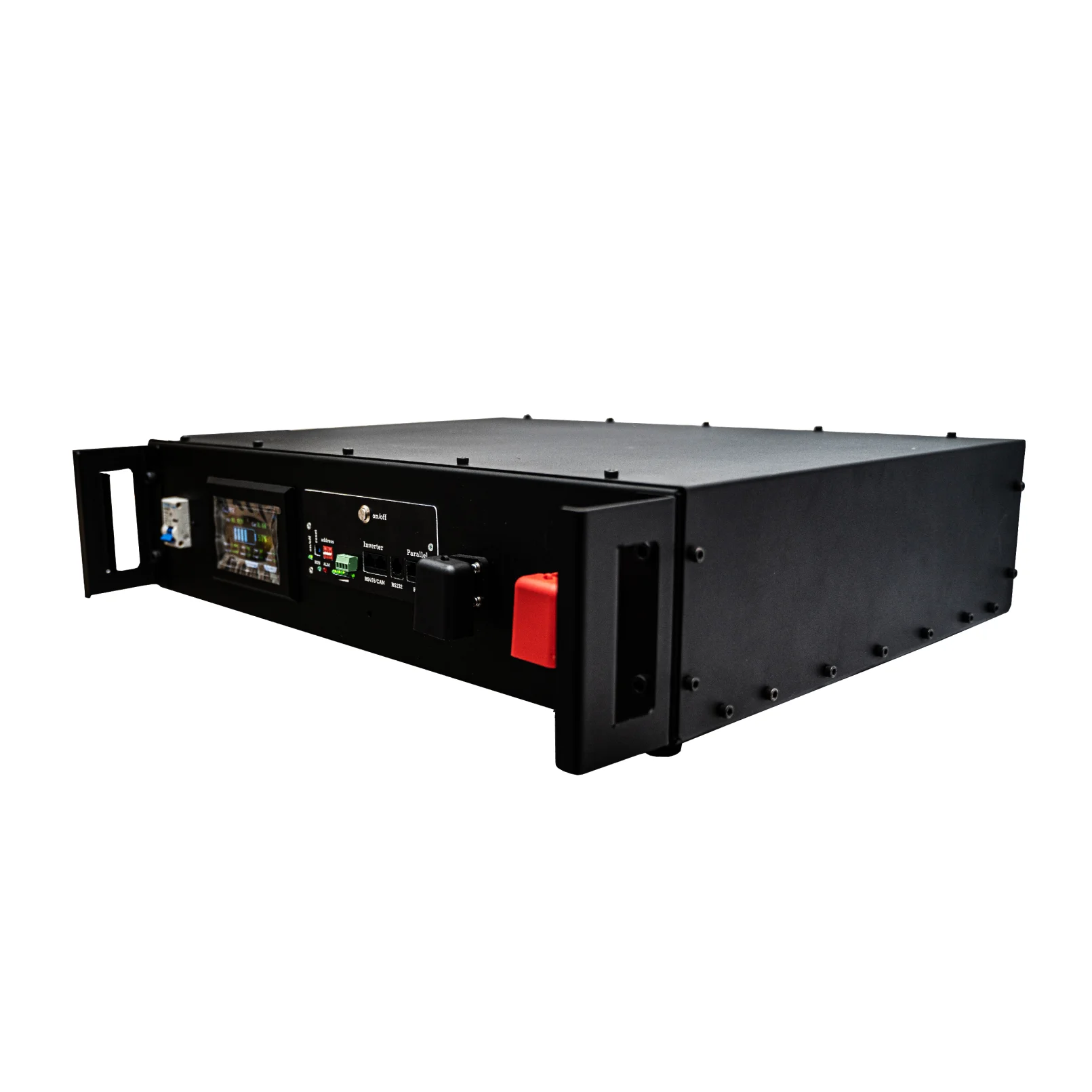
A 48 V battery for a hybrid inverter is the most expensive part of a home backup system. Building one yourself is realistic if you understand the layout and take your time. This article covers how to work out the S/P layout, choose a BMS and assemble the battery so it lasts for years.
S and P: what the numbers mean
- S (series) adds voltage. Capacity stays the same.
- P (parallel) adds capacity. Voltage stays the same.
A LiFePO4 cell is 3.2 V nominal. For a "48 V" system you need 16 cells in series (16S): 16 × 3.2 = 51.2 V nominal. A fully charged pack reaches up to 58.4 V (3.65 V per cell); an empty one sits around 40–44 V.
16S1P means 16 cells in series in a single string. 16S2P means each of the 16 positions holds two cells in parallel. Cells are first paralleled into groups, then the groups are connected in series. That way the BMS sees exactly 16 "cells" and monitors every group.
How much energy you get
Energy = nominal voltage × capacity.
- 16S1P with 280 Ah cells: 51.2 V × 280 Ah = 14,336 Wh, i.e. ≈ 14.3 kWh.
- 16S1P with 100 Ah cells: 51.2 × 100 = 5,120 Wh (5.1 kWh).
- 16S2P with 100 Ah cells: 51.2 × 200 = 10,240 Wh (10.2 kWh).
To see how many hours your home will run on such a battery, use the autonomy calculator.
Choosing a BMS
The BMS is the board that disconnects the battery on overcharge, over-discharge, overload, short circuit and unsafe temperature. The safety of the whole build depends on it.
Current. Work out the maximum discharge current: inverter power ÷ minimum battery voltage ÷ efficiency.
- 5 kW inverter: 5,000 ÷ 46 V ÷ 0.92 ≈ 118 A → a 150–200 A BMS.
- 8 kW inverter: 8,000 ÷ 46 ÷ 0.92 ≈ 189 A → a 200–250 A BMS.
Check that the cells can handle it too: datasheets for large prismatic cells often list 0.5C as the standard rate, i.e. 140 A for 280 Ah. If you need more, go 2P.
Inverter communication. For a hybrid inverter, choose a BMS with CAN or RS485 and a protocol your inverter supports. The inverter then sees the real state of charge and temperature and manages charging itself.
Balancing. Passive balancing bleeds off excess as heat at 30–150 mA — too little for 280 Ah cells. For large packs, a BMS with a 1–2 A active balancer or a separate active balancer is the better choice.
Preparing the cells: top balancing
Even cells from one batch have slightly different charge levels. Assembled as they are, the pack will hit the upper limit of its weakest cell.
- Use cells from one batch, matched by capacity and internal resistance.
- Measure each cell's voltage: they should differ by no more than a few hundredths of a volt.
- Connect all cells in parallel and charge them with a bench power supply to 3.65 V with current limiting.
- Hold until the current drops almost to zero. For sixteen 280 Ah cells this can take a day or longer — do not rush.
Assembly: busbars, nickel, compression
- Busbars. For prismatic cells use copper or aluminium busbars rated for your current. Clean the contact surfaces and tighten bolts with a torque wrench to the datasheet value. Flexible busbars cope better with slight cell expansion.
- Nickel strip. Cylindrical LiFePO4 cells are joined only by spot welding pure nickel strip. Never solder cells: the heat damages them. Nickel-plated steel runs hotter, so for high currents use several layers of pure nickel or copper-nickel bars.
- Compression. Large prismatic cells "breathe" during cycling. They are assembled in a frame with end plates and threaded rods to keep even, moderate pressure — datasheets often state a force of around 300 kgf. Put insulating sheets between cells.
- Cables and protection. For 150 A use at least 35 mm² copper, for 200 A 50 mm², and keep runs short. Fit a fuse of the right rating at the positive terminal plus a DC breaker or battery switch.
Safety while working
- Insulated tools, no rings or watches.
- Cover any terminals you are not working on. A short circuit at 51 V from a large pack turns metal red-hot instantly.
- Make the power connections between groups last, and connect the BMS strictly by its manual.
- Keep a fire extinguisher nearby. Do not charge the battery below 0 °C.
Testing before first use
- Balance leads. Connect the BMS in order (B0, B1 … B16) and measure with a multimeter after each lead: 3.2 → 6.4 → 9.6 V and so on. Getting the order wrong can destroy the board.
- First charge at low current; watch each cell's voltage in the BMS app.
- Capacity test. Discharge the pack with a known load to cut-off and compare the Wh you got with the calculation.
- Heat. After an hour under load, check busbars and terminals by touch or with a thermometer. A hot joint means a loose bolt or a dirty contact.
- Inverter settings. Charge voltage around 56.8 V (3.55 V per cell), float around 54 V, cut-off no lower than 48 V under load.
Next steps
To get the number of cells, the BMS and busbars right, try the DIY configurator on the home page: it puts together a kit for the voltage and capacity you need. Cells, BMS boards, balancers, busbars and enclosures are in the DIY parts section. If anything is unclear, message us before you buy: asking twice is cheaper than rebuilding a battery.
Power at home, no generator
LiFePO4 power stations and batteries in Kyiv. Shipped by Nova Poshta once stock is confirmed.
Read next
-
How long will a fridge run on a power station?
A simple formula for fridge runtime on a power station, compressor startup surge explained, and worked examples for 1,024, 2,048 and 5,120 Wh.
-
LiFePO4 vs Li-ion: which battery is right for home
3,000–6,000 cycles vs 500–1,000, safety, weight, cold weather and cost per cycle: an honest LiFePO4 vs Li-ion comparison for home backup power.